To start with a car engine design in Solidworks, you must understand what makes a piston work. Pistons have cylindrical shapes, and the process of modeling one starts with a sketch of its revolution. This sketch should be black, as it indicates that it is fully constrained. Next, you must model the connecting rod, which is symmetrical in shape. Lastly, you should consider the constraints that exist between the parts.
Flow simulation
Flow simulation for car engine design in SolidWorks can simulate many different aspects of the combustion process. The application can analyze STEP or IGES files. Simply go to Tools > Add-Ins and check the appropriate box. A simulation will begin. The software can analyze various kinds of solid geometry, including fuel-air mixtures, vapor-liquid interfaces, and fluid-solid interfaces. It can also analyze a variety of different flow phenomena, including fugitive fuel gas.
Once you’ve defined your unit system, you can now begin the simulation. Start by clicking “Add Unit System” in the Flow Simulation analysis tree. You can also change the unit system for the simulation. For instance, the Y and Z components will be renamed to drag and lift, respectively. Next, right-click “Control55mph” and choose “Run”. The Solver window will appear, displaying a log of each step of the solution process.
RealView graphics
If you’re planning on creating an engine design for a car, you’ll need a powerful workstation with RealView graphics. RealView graphics give you the ability to visualize and share complex VBOs and geometry. RealView is available in Solidworks 2009 and later. The latest certified drivers are required to run the software. You’ll also need to have a Professional-grade graphics card to use RealView.
The RealView graphics in Solidworks are more realistic than in traditional CAD software. With this technology, you can view your designs in 3D. These images are more detailed and realistic, and even the smallest details can be easily identified. RealView graphics also give you the ability to use advanced shading and reflections in real time. RealView is ideal for large-scale projects and has improved performance when working with complex models.
PhotoView 360
Using PhotoView 360 for car engine design in SolidWorks is a fantastic way to showcase your work to a large audience. With the advanced modeling tools available, it is possible to capture a realistic simulation of the car engine with a few clicks. In the motion study window, move to a specific frame and press the Final Render button in the Render Options ribbon. To check the results, you should compare the final render to the motion blur.
After creating the model of the car engine, you can move it to the exact position and align it using the camera. In SolidWorks, you can select the front plane, base, and midplane to be coincident. This enables you to easily align the engine with the car chassis and make the necessary adjustments. You can also make sure that the engine and chassis are set to coincident based on the distance relation.
Constraints between parts
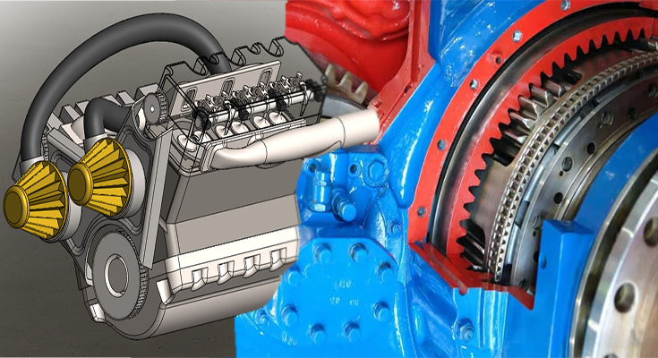
The process of designing an entire engine from scratch began with sketches. In Solidworks, the various parts were designed individually, tested, and then reconfigured to meet assembly specifications. Using a CMM, we were able to verify the accuracy of critical dimensions. In order to create a model that accurately depicts the entire engine, we needed to include all factory bolted-on accessories. After creating the model, we divided it into 25 individual components.
The constraint tool in Solidworks allows you to apply alignment constraints to parts and assemblies. It helps maintain the spatial relationship between parts, IntelliShapes, and assemblies. Several types of constraint properties can be used, including Align, Mate, and Parallel. Each constraint type is used to create a different conditional relationship between two parts or assembly components. Some examples are shown below.
Modeling of the piston
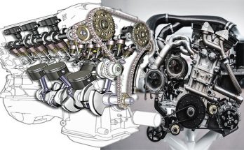
When you are creating a car engine, the piston is one of the busiest parts in the entire engine. During its revolution, the piston will face multiple thermal and mechanical forces. Ideally, the piston will take on a cylindrical shape when working at its optimum temperature, but the process can be complex and time-consuming if you don’t have the right tools. Modeling the piston in Solidworks allows you to see the internal pressures, temperatures, and more in a single model.
The process of designing a car engine in SolidWorks begins with sketches of the various parts. Once you’ve determined the exact location of every part, you can add constraints to allow them to move relative to each other. For example, a two-stroke engine has six pistons, each connected to a cylinder on the crankshaft. The crankshaft mates with the pistons in the engine shell through the front end hole. Lastly, the motor is placed on the crankshaft to turn it, and that causes the pistons to mostion.