 Prior to World War II, these engines had been utilised just about exclusively on submarines. In this arrangement, a carburetor 62, having a gasoline feedline 63 and a two-branch intake line 64 extending to each crankcase, is mounted on a single side of the engine. This is accomplished in a conventional manner by giving a ridge 60 on the face of the major piston 43 which traverses the piston involving the diametrically opposed inlet and exhaust ports.
It is contemplated that the flywheels 37 will have sufficient inertia and momentum to permit the crank shafts to smoothly roate by way of this return cycle, and it is to be noted that where the engine is composed of two 01 far more cylinders, no issue will exist mainly because the cranks can be timed to present a substantially continuous driving torque upon the engine shafts.
The exhaust port 46, positioned close to the base of the cylinder, is generally closed by the elongated skirt of the piston 43 and opens by movement of the face of the piston therepast as the primary crankshaft moves to bottom dead center and again closes as the crankshaft moves past bottom dead center. Other rewards of modularity contain optimized engine performance, lowered emissions, and an extended solution line. FIGURE 18 is a sectional strategy view of a single cylinder, two cycle, opposed-piston engine comparable to the view shown at FIG.
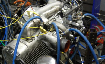
Efficient combustion in the opoc engine is achieved by very carefully managing the exchange of exhaust gas with fresh air/fuel, by precisely controlling the opening and closing of the intake/exhaust ports, by utilizing our electrically controlled turbocharger to dynamically adjust program stress, and by employing state-of-the-art side-mounted direct-injection injectors to deliver extremely atomized fuel into the combustion chamber which capabilities an revolutionary piston bowl design.
Opoc® is a truly modular engine, which means two (or a lot more) engine modules can be coupled together with an electrically controlled clutch. FIGURE 16 illustrates the position of the pistons at the finish of the operate cycle when the secondary piston is 90 degrees before its prime dead center and the principal piston is at bottom dead center as at line 16 at FIG. FIGURE 13 is a diagrammatic chart illustrating the comparative piston movements of the engine illustrated at FIGS. The engine runs on the two-stroke cycle, so there is combustion and a energy stroke each and every time the opposing sets of pistons move with each other, compressing the intake charge for ignition.


